
Así se fabrica un transformador EMINSA
Desde la planificación y el diseño hasta las pruebas eléctricas finales, nuestro proceso de manufactura está documentado, controlado y validado en cada etapa para garantizar calidad y cumplimiento con los estándares IEEE/ANSI.
9 Etapas, 1 Transformador Confiable
Cada unidad pasa por un proceso estructurado, controlado y documentado con verificación de Plan de Control en cada estación, desde la materia prima hasta el etiquetado y despacho.
 1Etapa 1 de 9
Diseño eléctrico y mecánico
Planificación y Diseño
El proceso comienza con la apertura de la orden de producción. El equipo de diseño eléctrico define todas las características eléctricas del transformador, y el departamento de diseño mecánico desarrolla su diseño estructural a partir de esas especificaciones. El software carga el modelo completo con el Bill of Materials de todos los insumos.
- Apertura de orden de producción (Planificación)
- Software: carga del modelo y Bill of Materials con todos los insumos
- Diseño Eléctrico: características eléctricas completas del transformador
- Diseño Mecánico: diseño estructural basado en especificaciones eléctricas
- Revisión del diseño vs. controles de calidad antes de continuar
 2Etapa 2 de 9
Estación BT y AT
Inspección de Materia Prima y Bobinado
Antes de iniciar el bobinado se realiza una revisión exhaustiva de la materia prima. Luego se procede al corte de papeles aislantes y manufactura de formaletas, seguido del bobinado de devanados de baja y alta tensión con controles estrictos de número de vueltas, tensión mecánica del conductor y aislamiento intercapas.
- Inspección de materia prima: espesor y grado de lámina magnética
- Verificación de certificados de cobre / aluminio e integridad del aislamiento
- Corte de papeles aislantes y manufactura de formaleta (precisión dimensional ± tolerancia según plano)
- Bobinado Baja Tensión (BT): número de vueltas, tensión mecánica del conductor, aislamiento intercapas
- Bobinado Alta Tensión (AT): mismos controles críticos de calidad
- Verificación de cumplimiento del Plan de Control antes de continuar
 3Etapa 3 de 9
Estación de corte y ensamble de núcleo
Corte y Armado del Núcleo Magnético
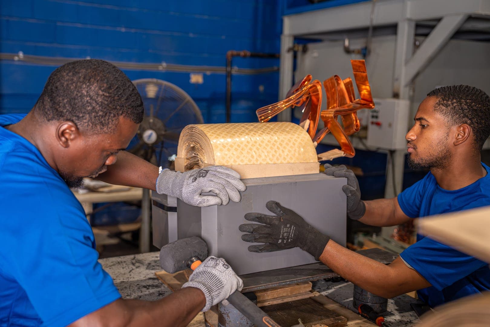
El núcleo magnético se corta con precisión dimensional controlada, verificando que las rebabas estén por debajo del límite permitido y que la secuencia de laminación sea correcta. Luego se realiza el apilado y armado del núcleo con alineación Step-Lap, compresión uniforme y torque de sujeción especificado.
- Corte de Núcleo Magnético: precisión dimensional (± tolerancia especificada)
- Rebabas < límite permitido y secuencia correcta de laminación
- Apilado y Armado del Núcleo: alineación Step-Lap
- Compresión uniforme y torque de sujeción según especificación
- Verificación de cumplimiento del Plan de Control antes de continuar
 4Etapa 4 de 9
Transporte, prensado y horno
Prensado y Secado de Bobinas
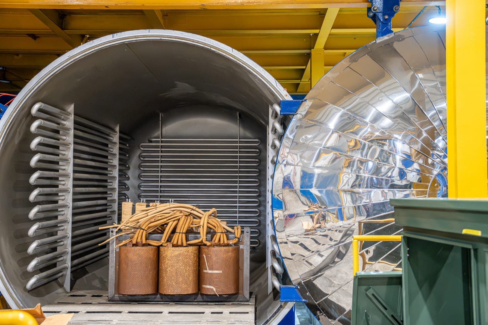
Las bobinas terminadas pasan por el proceso de prensado (Coil Pressing), donde se controla la altura final medida respetando las dimensiones nominales de BT y AT. Luego ingresan al horno de secado a temperatura entre 90 °C y 110 °C según diseño durante 12 horas, registrando los resultados en el checklist de control de temperatura del horno.
- Coil Pressing Process: evitar aplicar fuerza excesiva, verificar altura final medida
- Respetar altura nominal de BT y AT de la bobina ensamblada; medición final documentada
- Transporte de bobina prensada al horno
- Parámetros del Horno validados antes de cargar la bobina
- Secado de Bobina (Coil Drying): 90 °C – 110 °C según diseño, 12 horas
- Registro de resultados al salir del horno en el checklist 'Oven Temperature Control, Operational Checklist'
 5Etapa 5 de 9
Inserción de núcleo, brida y conexiones
Ensamble de Parte Activa (Pre-Tanque)
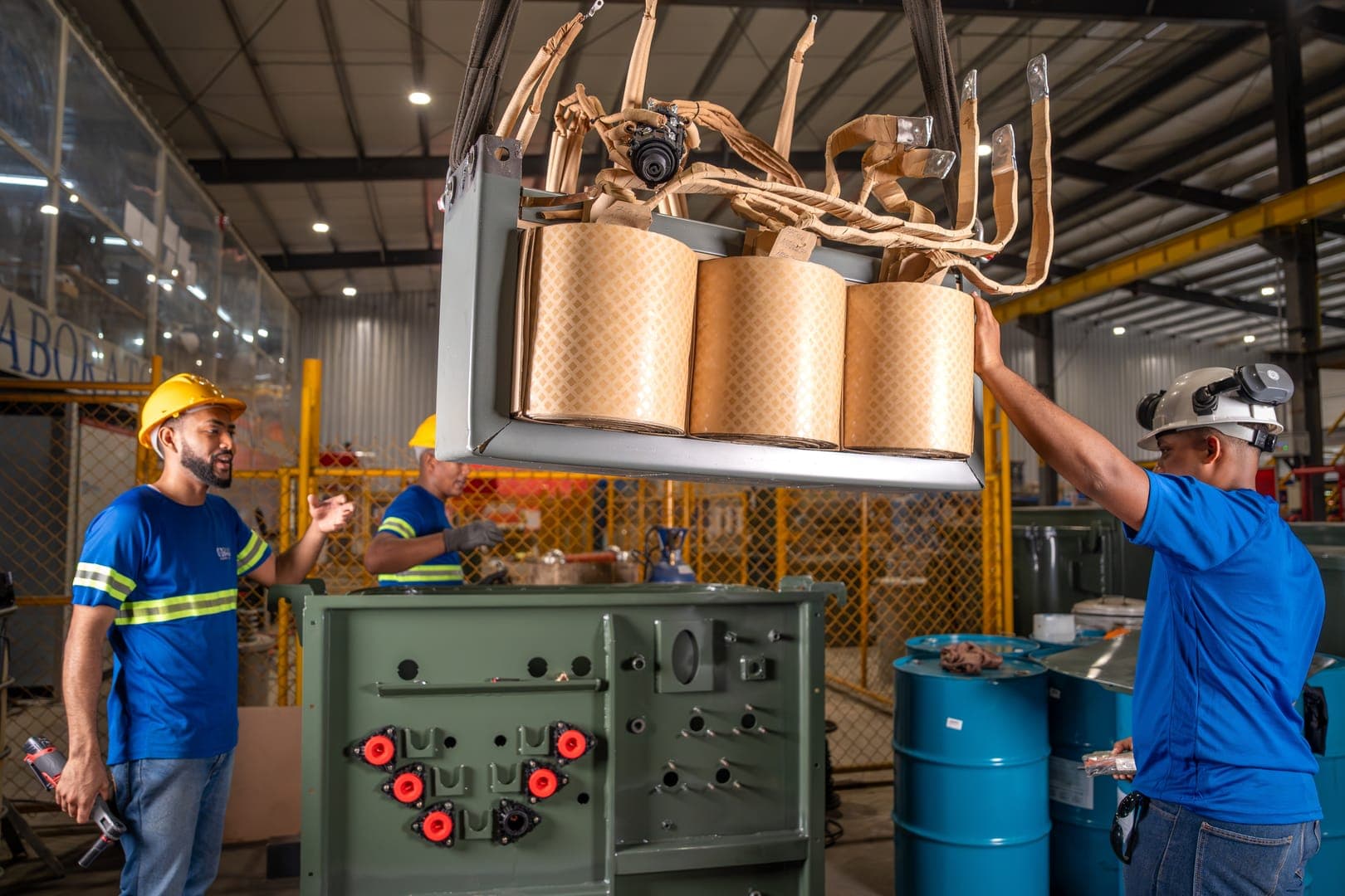
El núcleo se inserta y ensambla en las bobinas con enfoque en centrado axial, espaciamientos radiales y ajuste mecánico. Se instala la brida verificando la superficie, la junta (gasket) y el torque. Finalmente se realizan las conexiones externas previas al entanque, identificando correctamente los terminales y respetando las distancias dieléctricas.
- Inserción y/o ensamble del núcleo en las bobinas: centrado axial, espaciamientos radiales, ajuste mecánico
- Instalación de Brida: inspección de superficie, verificación de junta (Gasket), control de torque
- Conexiones Externas Previas al EnTanque: identificación correcta de terminales
- Torque en conexiones atornilladas y distancias dieléctricas verificadas
- Verificación de cumplimiento del Plan de Control antes de continuar
 6Etapa 6 de 9
Proceso paralelo — corte, soldadura y pintura
Metalmecánica del Tanque
En paralelo con la manufactura de la parte activa, el departamento de metalmecánica fabrica el tanque mediante corte láser de planchas, formado/doblado de paredes y tapa, soldadura estructural completa y preparación de superficie. Después de la prueba de hermeticidad e inspección dimensional, el tanque recibe su sistema de pintura (primer, capa intermedia y acabado) y la inspección mecánica final antes de ser liberado por Calidad.
- Corte con Máquina Láser: inspecciones previas al arranque (Kick-off Checklist), corte y verificación dimensional
- Forming / Bending: conformado de paredes laterales, tapa e inspección dimensional
- Soldadura Completa: soldaduras estructurales, bridas de boquillas y refuerzos
- Grinding y preparación de superficie: alisado de soldaduras, eliminación de rebabas, limpieza
- Prueba de Hermeticidad (Leak Test): prueba de presión de aire, inspección con solución jabonosa, tiempo de retención
- Inspección Dimensional: altura del tanque, planitud de brida, alineación de radiadores, posición de orificios de pernos
- Preparación de Superficie: sandblasting / granallado, verificación de rugosidad y limpieza
- Proceso de Pintura: aplicación de primer, capa intermedia, capa final y control de tiempo de curado
- Inspección Mecánica Final: visual, dimensional, reporte de espesor de pintura, aprobación del leak test y liberación por Calidad
 7Etapa 7 de 9
Recepción del tanque y tanqueo
EnTanque
Una vez liberado el tanque por Calidad (pintado y curado), se transporta al área de tanqueo.
- Recepción del Tanque desde Metalmecánica (pintado, curado y liberado por Calidad)
- Transporte del tanque aprobado hacia el área de tanqueo
- Integración de la parte activa dentro del tanque
- Verificación de cumplimiento del Plan de Control
 8Etapa 8 de 9
Oil Treatment & Tank Filling
Tratamiento de Aceite y Llenado al Vacío
El aceite dieléctrico se filtra y se aplica vacío al transformador ya tanqueado. El proceso de llenado al vacío garantiza la impregnación completa del aislamiento y la ausencia de burbujas de aire. Se siguen las Visual Aids del proceso Oil Filtered & VA Vacuum and Oil Filling.
- Oil Filtered: filtrado y tratamiento del aceite dieléctrico
- VA Vacuum: aplicación de vacío al transformador antes del llenado
- Oil Filling: llenado al vacío para impregnación total del aislamiento
- Seguimiento de Visual Aids 'Oil Filtered & VA Vacuum and Oil Filling'
- Verificación de cumplimiento del Plan de Control antes de pasar a pruebas
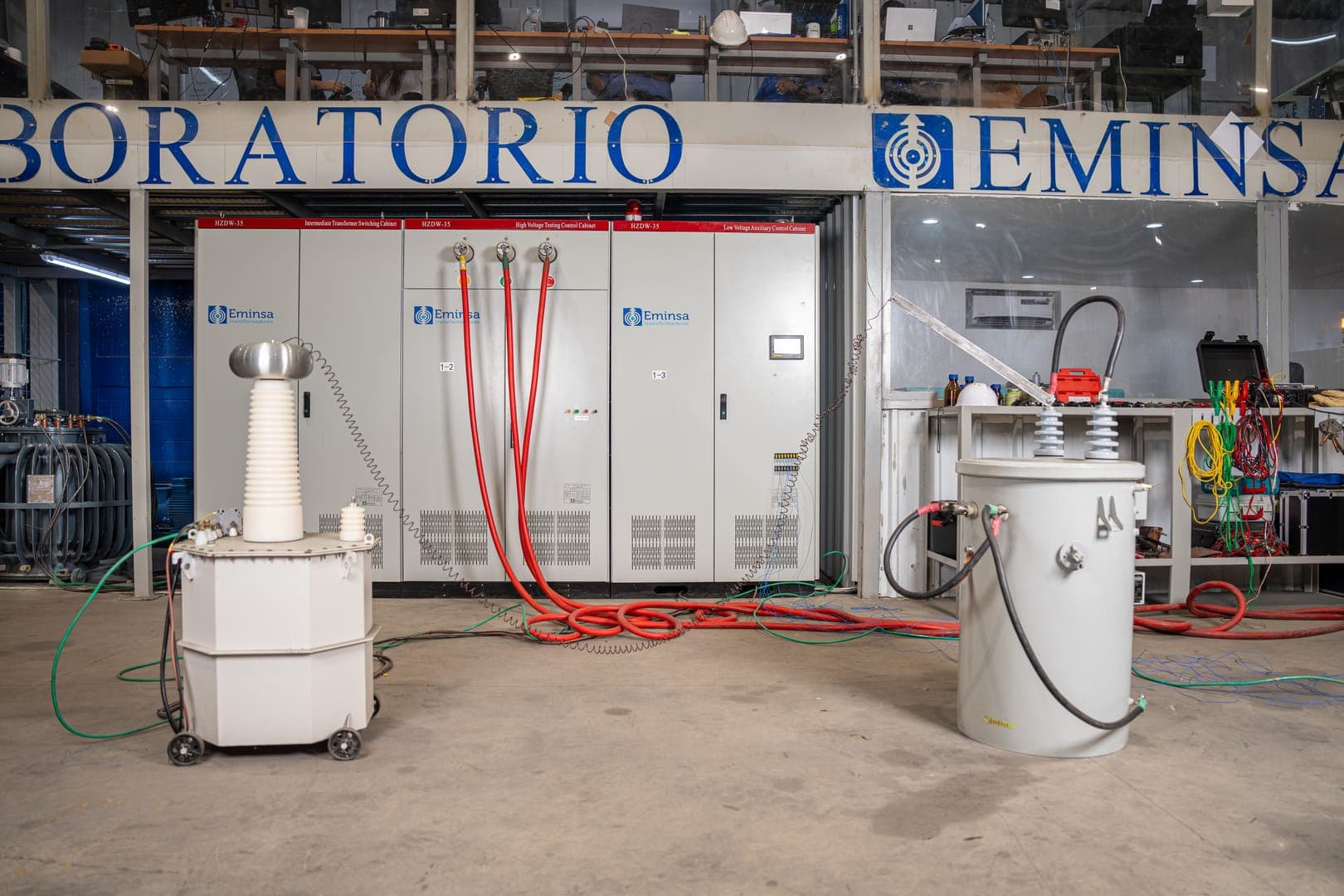 9Etapa 9 de 9
Testing, Inspection & Packaging
Pruebas Eléctricas, Inspección Final y Despacho
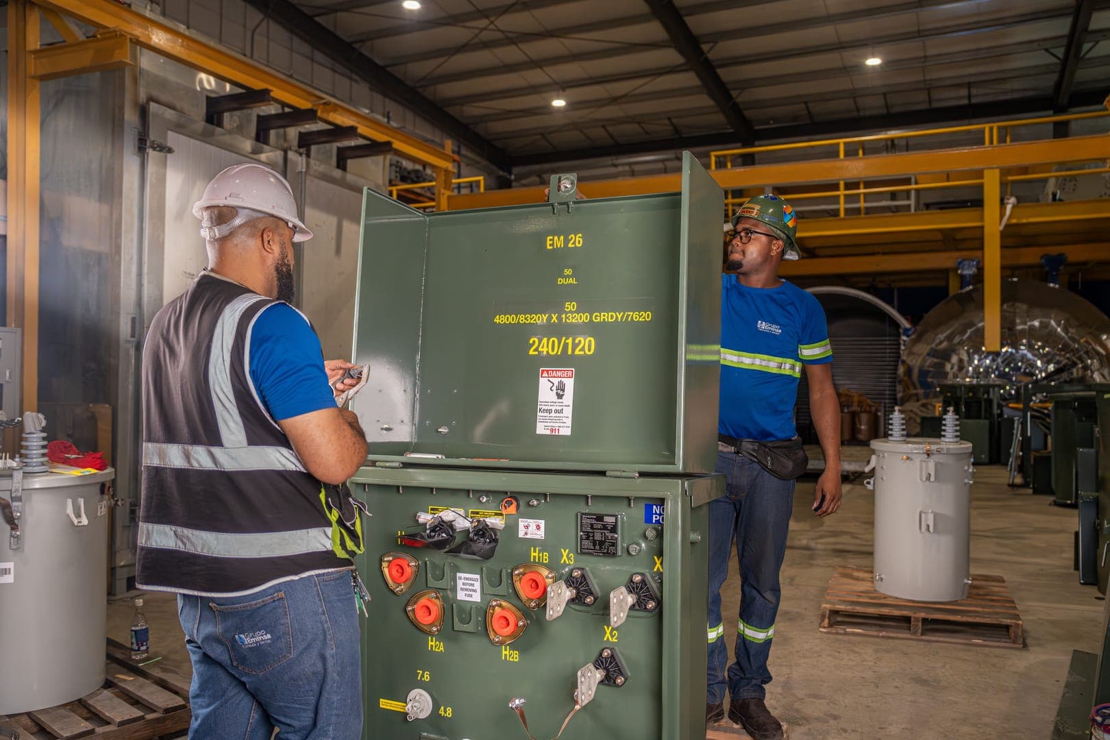
Cada transformador pasa por un protocolo completo de pruebas eléctricas según IEEE C57 en la estación de testing. Una vez que los resultados son aprobados (Pass), se procede al ensamble del gabinete, la inspección final y empaque, y finalmente el etiquetado y embalaje para despacho.
- Testing & Results: pruebas eléctricas completas según IEEE C57
- Verificación de cumplimiento del Plan de Control en pruebas
- Ensamble del Gabinete (aprobado por Plan de Control)
- Final Inspection & Packaging: inspección visual, dimensional y de acabados
- Etiquetado y Empaque: placa de datos, embalaje para transporte y despacho
Calidad documentada en cada etapa
¿Listo para cotizar su transformador?
Cuéntenos sus especificaciones y nuestro equipo técnico preparará una propuesta personalizada con los tiempos de entrega de su proyecto.